A practical workroom guide to cord-operated sloped drapery, pleat calculations, and custom buckram template construction.
Sloped windows require a different approach to drapery construction than conventional rectangular windows.
With a standard horizontal track, the heading remains level and the pleats are constructed at a consistent height. With sloped drapery, the heading must follow an inclined track while the fabric folds hang vertically and the bottom hem remains level.
The challenge is not simply cutting the top of the fabric at an angle.
The track mechanism, leading edge, pleat distribution, and buckram construction must all be considered before the heading is made.
This article documents a practical workroom method used to construct a fully operable sloped drapery sample. It covers the track components, actual measurements, pleat calculations, and the preparation of a custom buckram template.
The template-making principle can be applied to straight sloped drapery installations with different dimensions and inclines. However, the specific measurements and edge allowances must be adapted to the track system and installation conditions.
1. Understanding the Sloped Drapery Track System
Before measuring or cutting the fabric, it is important to understand how the track operates.
Unlike a horizontal curtain track, a sloped track is affected by gravity along its incline. Without an appropriate control mechanism, the drapery may slide toward the lower end.
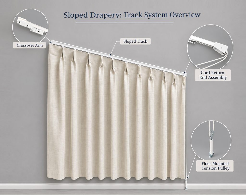
The sample shown here uses a cord-operated track with several important components.
Crossover Arm
The crossover arm supports the leading section of the drapery and allows the heading to extend beyond the nominal coverage position.
Its projection must be considered when establishing the required finished coverage width.
Cord Return End Assembly
The cord return end assembly redirects the operating cord at the end of the track, allowing the cord system to function along the inclined installation.
Floor-Mounted Tension Pulley
The floor-mounted tension pulley maintains tension in the operating cord through a spring-loaded mechanism.
In this sample, the complete cord-control system allows the drapery to travel along the inclined track and remain in the selected position without freely sliding toward the lower end.
The positioning function depends on the complete operating system rather than the tension pulley alone.
These components are relevant to construction because they affect the leading edge, overall coverage, and the relationship between the drapery and the track.
2. Measuring and Planning the Sloped Drapery
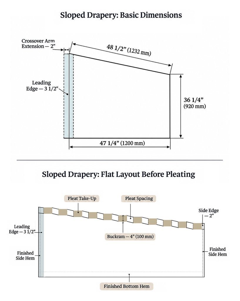
The following measurements were used for this sample.
| Measurement | Sample dimension |
|---|---|
| Nominal horizontal coverage | 47 1/4″ (1,200 mm) |
| Sloped track length | 48 1/2″ (1,232 mm) |
| Right-side finished height | 36 1/4″ (920 mm) |
| Crossover arm extension | 2″ (50 mm) |
| Leading edge | 3 1/2″ (90 mm) |
| Side edge | 2″ (50 mm) |
| Buckram height | 4″ (100 mm) |
Certain inch measurements are shown with rounded metric values used in the actual workroom calculations.
Cover Width and Crossover Arm Extension
The nominal horizontal coverage of this sample is 1,200 mm.
However, the crossover arm projects approximately 2″ (50 mm) beyond that width.
The required Cover Width is therefore:
Cover Width = 1,200 + 50 = 1,250 mm
This dimension already includes the 3 1/2″ (90 mm) leading edge.
The crossover arm extension and the leading edge serve different purposes. The 50 mm extension increases the required coverage beyond the nominal width, while the 90 mm leading edge forms part of the finished drapery construction.
They should not both be added again to the Cover Width.
Why the Side Edge Is Calculated Separately
This sample uses an inside-mounted arrangement.
An additional 2″ (50 mm) side edge is provided at the outer end of the drapery to help reduce light leakage through the side gap.
For this reason, the side edge is treated as an additional allowance outside the 1,250 mm Cover Width.
It is also excluded from the fullness calculation.
This is a construction decision specific to the sample, not a fixed rule for every sloped drapery installation.
With another track system or mounting arrangement, the leading edge and side edge may require different dimensions or may be included in the coverage calculation.
Before calculating pleats, the workroom should establish which sections are included in the Cover Width and which are treated separately.
3. Calculating Pleat Spacing and Pleat Take-Up
For this sample, the pleat layout uses:
- Cover Width: 1,250 mm
- Leading Edge: 90 mm
- Number of Pleats: 11
- Number of Pleat Spacings: 10
- Fullness: 2.3×
- Side Edge: 50 mm, calculated separately
The 2.3× fullness is applied to the central pleated section, excluding the leading edge and side edge.
Calculate the Width Available for Pleat Distribution
Subtract the leading edge from the Cover Width:
1,250 − 90 = 1,160 mm
This is the finished coverage allocated to the pleated section.
Calculate Pleat Spacing
With 11 pleats, there are 10 spaces between them.
1,160 ÷ 10 = 116 mm
Pleat Spacing = 4.57″ (116 mm)
Calculate Total Pleat Take-Up
Apply 2.3× fullness to the pleated section:
1,160 × 2.3 = 2,668 mm
The 10 spaces occupy:
116 × 10 = 1,160 mm
The remaining material is taken up by the pleats:
2,668 − 1,160 = 1,508 mm
Total Pleat Take-Up = 1,508 mm
Calculate Take-Up per Pleat
1,508 ÷ 11 = 137.09 mm
Pleat Take-Up per Pleat = 5.40″ (137.1 mm)
Final Pleat Layout
| Component | Quantity | Dimension per section |
|---|---|---|
| Leading Edge | 1 | 3 1/2″ (90 mm) |
| Pleat Take-Up | 11 | 5.40″ (137.1 mm) |
| Pleat Spacing | 10 | 4.57″ (116 mm) |
| Side Edge | 1 | 2″ (50 mm) |
| Fullness | — | 2.3× |
The pleat distribution in this example is calculated using the horizontal coverage width rather than the sloped track length.
These calculated dimensions establish the layout for the custom buckram template.
4. Making the Sloped Buckram Template
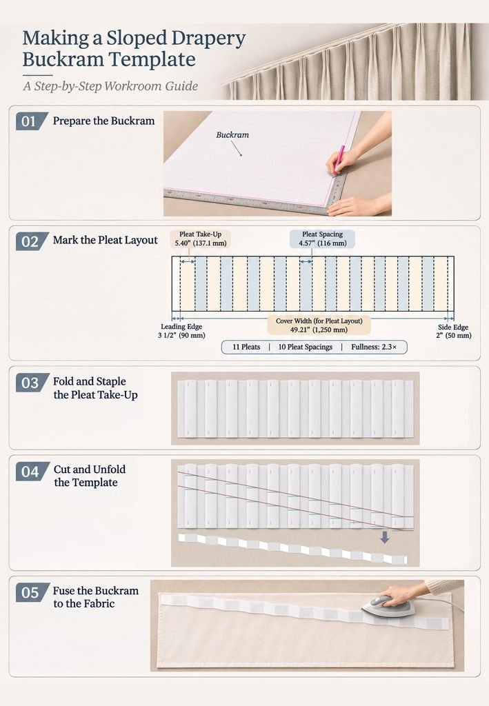
The most important part of this method is how the sloped heading shape is transferred into the buckram template.
Instead of cutting a continuous diagonal line across a completely flat strip, the pleat take-up areas are temporarily folded first.
The slope is then marked and cut while the template represents the reduced width of the pleated heading.
Sloped drapery can be made with either single-layer or double-layer construction. The buckram template-making principle remains the same, although the subsequent sewing and heading assembly sequence may differ.
This example follows a single-layer construction method.
Step 1 — Prepare the Buckram
Lay a sheet of buckram flat on the cutting table.
The sheet must be large enough to accommodate the vertical difference between the high and low ends of the sloped heading, with additional working allowance.
In this approach, approximately 10″ (25 cm) is allowed beyond the vertical height difference to provide sufficient room for marking, folding, and cutting.
Use a straightedge or square to establish the initial layout lines.
At this stage, the buckram remains completely flat.
Step 2 — Mark the Pleat Layout
Using the calculated dimensions, mark the pleat take-up sections and the spaces between them.
For this sample:
- 11 pleat take-up sections, each 5.40″ (137.1 mm)
- 10 pleat spacing sections, each 4.57″ (116 mm)
- Leading edge: 3 1/2″ (90 mm)
- Side edge: 2″ (50 mm)
Mark the boundaries of each section clearly.
The pleat take-up sections represent the material that will eventually be folded into the finished pleats.
The spacing sections represent the material that remains between the pleats.
Step 3 — Fold and Staple the Pleat Take-Up
Starting with the first pleat take-up section, bring its two marked boundary lines together.
Fold the material between those lines and press the folded section flat toward the left.
Temporarily secure the fold with staples.
Repeat this procedure for all 11 pleat take-up sections.
All pleat take-up folds must be pressed in the same direction — toward the left.
The 10 pleat spacing sections remain flat and unfolded.
Once the folds are secured, the template represents the reduced width of the heading after the pleat allowances have been taken up.
This temporary arrangement makes it possible to establish the sloped heading line in relation to the actual pleat positions.
Step 4 — Mark, Cut, and Unfold the Sloped Template
Keep all pleat take-up sections folded and secured.
Using the sloped window measurements, draw two parallel inclined reference lines across the folded buckram.
The vertical distance between the two lines is 4″ (100 mm), representing the required buckram height.
The cutting method differs between the pleat spacing sections and the folded pleat take-up sections.
Pleat Spacing Sections
Cut along the sloped reference lines.
These sections retain the incline corresponding to the sloped track.
Pleat Take-Up Sections
At each folded pleat take-up section, cut horizontally along the marked level lines, cutting through the entire folded section.
This produces level edges in the areas that will later be formed into pleats.
After cutting, remove the temporary staples and unfold the buckram.
The completed template has alternating sloped and level sections.
The sloped sections correspond to the spaces between the pleats, while the level sections correspond to the pleat take-up areas.
This alternating profile is the defining feature of the template.
Step 5 — Fuse the Buckram to the Drapery Fabric
Lay the drapery fabric flat on the cutting table.
Position the fully opened buckram template along the heading area, following the intended sloped profile.
In this sample, the side hems and bottom hem are prepared before completing the heading.
Using the appropriate pressing conditions for the fabric and interfacing, carefully fuse the buckram to the fabric.
The buckram must remain fully opened during this process.
Once the interfacing is secured, finish the heading edge and construct the pleats at the previously marked positions.
The completed heading follows the sloped track, while the drapery folds hang vertically and the bottom hem remains level.
5. Workroom Considerations and Practical Applications
The buckram template-making principle described in this article can be applied to straight sloped drapery installations with different angles and dimensions.
However, the individual measurements must be established according to the track system, hardware, and mounting arrangement.
Several considerations are particularly important.
Track Components
Confirm the actual crossover arm extension, operating mechanism, and track end arrangement before establishing the required coverage.
Leading Edge and Side Edge
Determine their finished dimensions and whether they are included in the Cover Width. Inside-mounted installations may require additional side coverage to reduce light leakage.
Pleat Distribution
Calculate the spacing and take-up consistently, using the appropriate finished coverage definition for the selected construction method.
Fabric and Heading Construction
The template principle remains applicable to single-layer and double-layer drapery, but the subsequent assembly sequence must suit the chosen fabric construction.
Installation and Operation
Check track load capacity, fabric weight, cord operation, and hardware installation requirements. Cord-operated systems must also comply with applicable safety requirements.
In the completed sample, the curtain could be moved along the inclined track, with vertical folds and a level bottom hem.
The result demonstrates how a carefully planned heading template can translate an inclined track into a workable drapery construction.
The key is not simply the slope itself, but the relationship between track coverage, pleat distribution, and the folded buckram pattern.
Related Reading
Sloped Drapery Construction Guide
Arched Drapery Construction Guide — A related workroom study covering curved track systems, pleat layouts, and shaped buckram templates.
Drapery Heading Styles: Construction Details
An overview of common drapery heading structures and construction methods.
Pinch Pleat Heading Finishes
A closer examination of buckram wrapping, stitching, and heading finishing techniques.
Pinch Pleat Drapery Calculator
A planning tool for conventional pinch-pleat drapery calculations. Sloped installations require additional consideration of the track geometry and edge allowances.
This article documents a practical workroom construction method using an actual sloped drapery sample. Dimensions and allowances should be adapted to the hardware, installation, and fabric selected for each project.