
Arched windows bring a distinctive architectural character to a room, but making drapery that follows a curved track requires more than shaping the top of a fabric panel.
The track, panel widths, pleat distribution, and heading construction all need to work together. When these details are properly coordinated, the drapery can follow the arch while maintaining a level bottom hem and a natural vertical fall.
In many ways, the construction process is similar to that of sloped drapery. Both begin with the actual track configuration, followed by panel measurements, pleat planning, and the preparation of a shaped buckram template.
The main difference lies in the geometry. A sloped heading follows a straight incline, while an arched heading must accommodate a continuously changing curve.
This journal entry looks at a two-panel arched drapery project, using the right panel to illustrate the measurements, pleat calculations, and template-making process.
The dimensions shown are specific to this project. They are intended to explain the construction approach rather than establish a universal set of measurements.
1. Understanding the Arched Track System
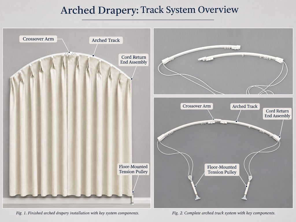
Before working out the fabric dimensions, it helps to understand how the track operates.
The system used in this project is a cord-operated, center-opening arched track. Its main components include the curved track sections, a crossover arm, cord-return end assemblies, and floor-mounted tension pulleys.
Each component plays a role in how the finished panels meet and move along the arch.
One detail worth considering early is the crossover arm.
When the curtains close at the center, the crossover arm allows one panel to extend beyond the meeting point of the two track sections, creating an overlap.
For this installation, the right panel requires an additional 1 1/2″ (38 mm) to accommodate that extension. The left panel follows the standard half-width measurement.
This extra width comes from the hardware arrangement, not from the arched shape itself.
A different track system may have a different crossover allowance, which is why it is useful to establish the hardware configuration before calculating the fabric.
2. Establishing the Arch Dimensions and Panel Layout
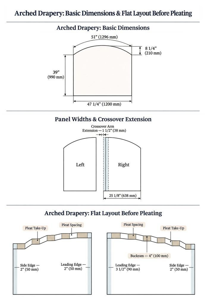
The example window has a symmetrical arched opening with the following measurements:
| Measurement | Project dimension |
|---|---|
| Horizontal width | 47 1/4″ (1,200 mm) |
| Height to the spring points | 39″ (990 mm) |
| Arch rise | 8 1/4″ (210 mm) |
| Curved top length | 51″ (1,296 mm) |
These measurements establish the basic proportions of the opening.
For actual fabrication, however, the heading shape must correspond to the installed track. Its mounting position and curvature are just as important as the dimensions of the window opening.
Accounting for the crossover arm
The overall horizontal width is 1,200 mm. Dividing it equally gives a base width of 600 mm for each panel.
The left panel follows this base measurement.
For the right panel, the crossover arm adds another 38 mm:
600 mm + 38 mm = 638 mm
The resulting right-panel finished cover width is approximately 25 1/8″ (638 mm).
In this project, that measurement includes the center leading edge but excludes the outer side edge.
This distinction becomes important when calculating the pleat layout.
Looking at the panels before pleating
The lower drawings in Image 2 show both panels laid flat, before the pleats have been formed.
The finished drapery will have a smooth arched heading, but the flat fabric layout looks quite different.
Along the shaped top edge, the pleat take-up sections alternate with the spaces between pleats. These sections are planned before sewing so that the fabric can be brought together at the correct positions.
The left and right layouts mirror the direction of the arch, while the bottom edges remain level.
The drawing also identifies the leading edges, side edges, and buckram positions that will guide the later construction.
3. Planning the Pleats: Right Panel Example
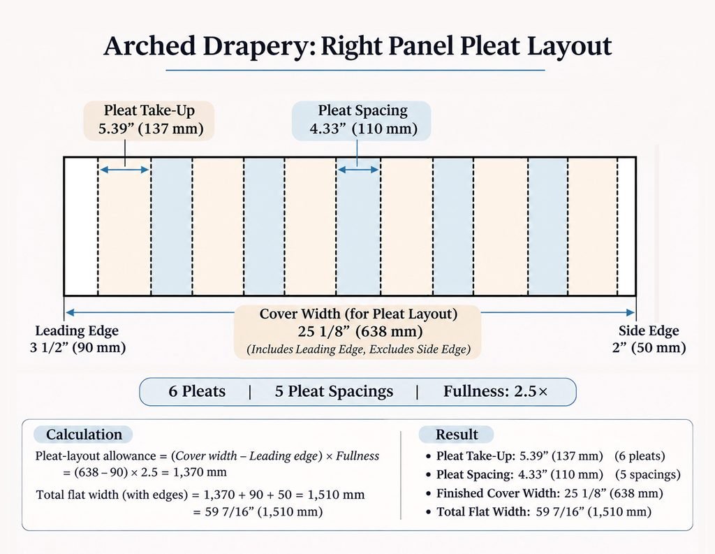
With the finished cover width established, the next step is to distribute the fabric between the pleats and the spaces separating them.
For this right panel, the selected construction uses six pleats, five spaces, and a 2.5× fullness allowance.
The working dimensions are:
| Item | Measurement |
|---|---|
| Finished cover width | 25 1/8″ (638 mm) |
| Leading edge | 3 1/2″ (90 mm) |
| Side edge | 2″ (50 mm) |
| Fullness | 2.5× |
| Number of pleats | 6 |
| Number of pleat spacings | 5 |
Finding the width available for pleat distribution
The finished cover width already includes the 90 mm leading edge.
After setting that portion aside, the remaining width for the pleat layout is:
638 − 90 = 548 mm
Applying the selected 2.5× fullness gives:
548 × 2.5 = 1,370 mm
This is the total flat fabric allocation for the pleat take-up sections and the spaces between them.
Distributing the pleats and spaces
For this layout, each of the five pleat spacings is assigned 4.33″ (110 mm) of flat fabric.
Together, those spaces account for:
5 × 110 = 550 mm
The remaining material is allocated to the six pleats:
1,370 − 550 = 820 mm
Dividing this evenly gives:
820 ÷ 6 = approximately 136.7 mm per pleat
Each pleat therefore requires about 5.39″ (137 mm) of take-up.
In practice, the values are distributed using the unrounded measurements so that small rounding differences do not accumulate across the heading.
Calculating the total flat width
The 1,370 mm allocation covers the pleats and their spacing. The leading edge and outer side edge must also be included in the flat layout.
1,370 + 90 + 50 = 1,510 mm
The total flat width before pleating is therefore approximately 59 7/16″ (1,510 mm).
It is helpful to distinguish this from the finished cover width:
Finished cover width — 25 1/8″ (638 mm)
The width covered by the panel after pleating, including the leading edge but excluding the outer side edge allowance.
Total flat width before pleating — 59 7/16″ (1,510 mm)
The full width used for this layout before the pleats are formed, including the leading and side edges.
Keeping these two measurements separate makes the pleat calculations easier to follow and avoids confusing the finished panel width with the fabric required to construct it.
4. Making the Arched Buckram Template
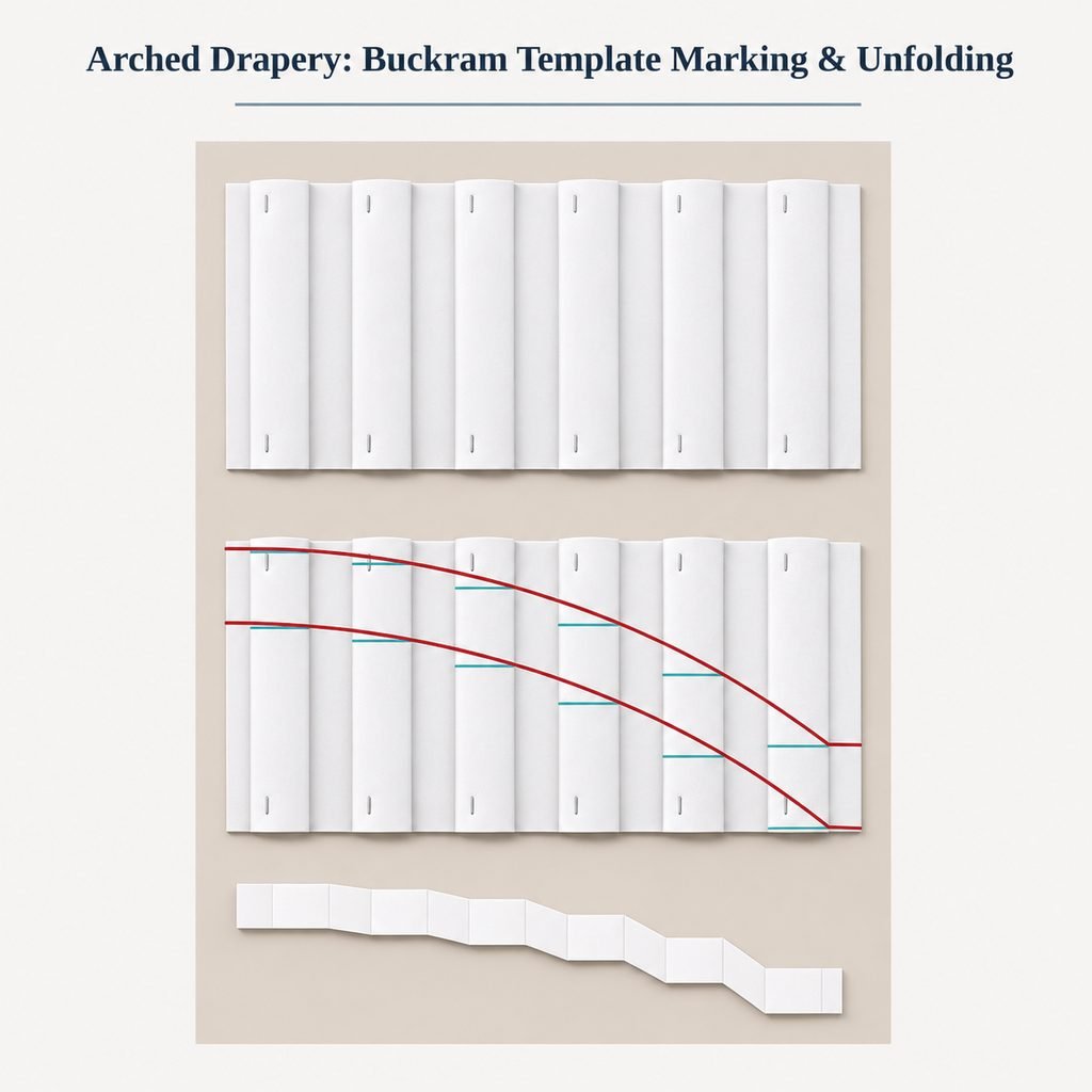
Once the pleat positions have been planned, the next task is to shape the buckram that will support the heading.
This project uses approximately 4″ (100 mm) wide buckram.
The method follows the same principle used for the sloped drapery template: the buckram is first folded at the planned pleat positions, marked and cut while folded, then opened out into its final shape.
Folding the buckram
The pleat take-up sections are folded according to the layout and temporarily secured.
At this stage, the folded buckram represents the distribution of the heading after the pleats have been formed.
Keeping the folds aligned with the planned pleat positions is essential. The resulting template will later need to correspond to the same marks on the flat fabric.
Marking the curved and horizontal cutting lines
With the buckram folded and secured, the arched outline can be marked.
Image 4 uses two colors to explain the cutting method.
Red lines — Arched Cutting Lines
The red curves establish the upper and lower boundaries of the shaped heading.
They follow the intended arch and reflect the gradual change in height along the track.
Blue lines — Horizontal Cutting Lines at Pleat Take-Up Sections
The blue marks identify the horizontal cutting lines within the folded pleat take-up sections.
This is an important detail.
Rather than continuing the red curve directly through every folded pleat section, those areas are cut along the marked horizontal lines.
The same principle is used in the sloped drapery template.
These horizontal sections allow the template, once unfolded, to retain the appropriate height at the pleat positions while following the changing profile between them.
The red and blue lines serve different purposes, but both are needed to create the intended heading shape.
Cutting and unfolding the template
After checking the markings, the buckram is cut along the appropriate curved and horizontal sections.
The temporary folds are then released.
Once opened out, the buckram no longer has a straight upper edge. Instead, it forms a stepped profile that corresponds to the planned pleat positions and the shape of the arch.
This stepped appearance is a result of the folding and cutting process, not a decorative design added afterward.
Before applying the template to the fabric, it is worth checking the direction of the curve, the number of pleat sections, and the alignment of the transitions.
The template and the fabric layout must correspond to one another.
5. Applying the Buckram to the Fabric
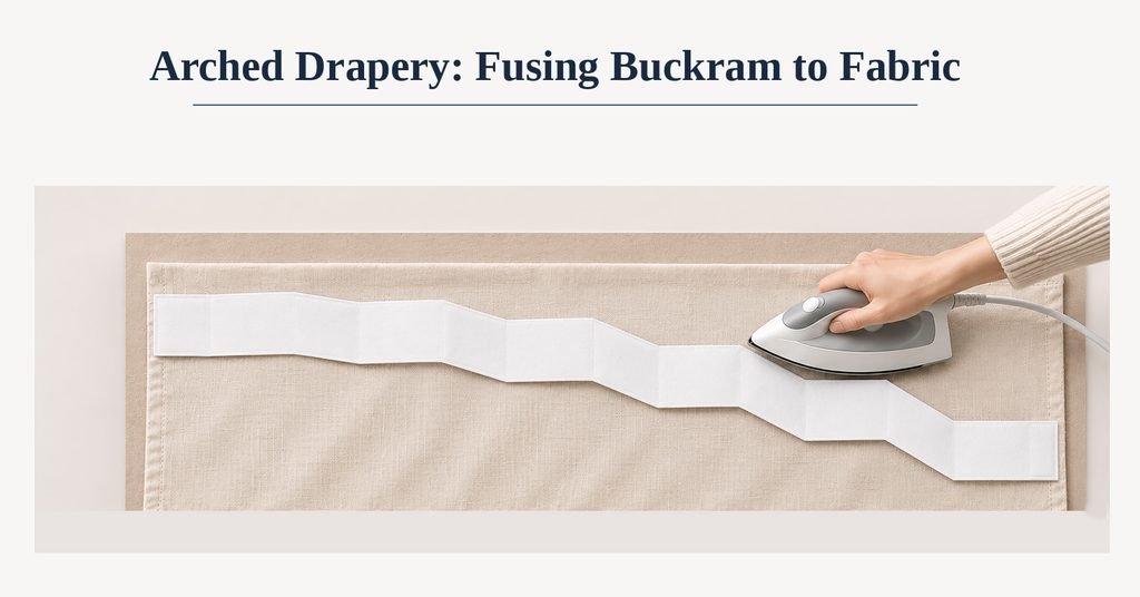
With the template complete, the shaped buckram can be positioned on the flat drapery fabric.
The fabric is laid out, and the buckram is aligned with the previously established pleat positions and heading direction.
Because the buckram has already been shaped to accommodate the arch, its upper and lower edges change direction along the length of the panel.
The transitions should correspond to the pleat marks rather than being positioned by eye.
For the fusible buckram used in this example, the material is bonded to the fabric in sections, following the appropriate pressing requirements for both materials.
Careful alignment during pressing helps prevent shifting, stretching, or distortion along the shaped heading.
Once the buckram is secured, the panel can proceed through the remaining heading construction, pleating, and finishing stages.
Arched drapery can be made with either single-layer or layered fabric construction. The same general template-making principle applies, although the sewing sequence may differ.
For this entry, the focus remains on the template and the relationship between the arch, the pleat layout, and the fabric.
6. What Arched and Sloped Drapery Have in Common
Although their outlines are different, arched and sloped drapery share much of the same construction logic.
Both begin with the actual track system.
The hardware determines the cover width, any required overlap, and the relationship between the two panels.
The planned pleat distribution then establishes how much flat fabric is needed and where the folds will be formed.
Finally, a shaped buckram template translates the track profile into a heading that can be constructed on the flat fabric.
The difference is primarily geometric.
A sloped heading changes along a straight incline, while an arched heading follows a continuous curve.
Understanding how to translate those shapes into a repeatable workroom process is more useful than relying on a single set of measurements.
Final Thoughts
Making arched drapery is not simply a matter of cutting the top of a conventional curtain into a curved shape.
The track, crossover arrangement, finished cover width, pleat distribution, and buckram template all influence the final result.
In this project, each step builds on the one before it: the hardware establishes the working dimensions, the dimensions guide the pleat layout, and the pleat layout determines how the buckram template is folded, marked, and cut.
The method shown here is one practical approach based on a particular track and fabrication arrangement. Different arches, hardware systems, and heading constructions may require adjustments.
What remains consistent is the value of understanding the structure before cutting the fabric.
A Practical Note: Finding the Center of an Arch
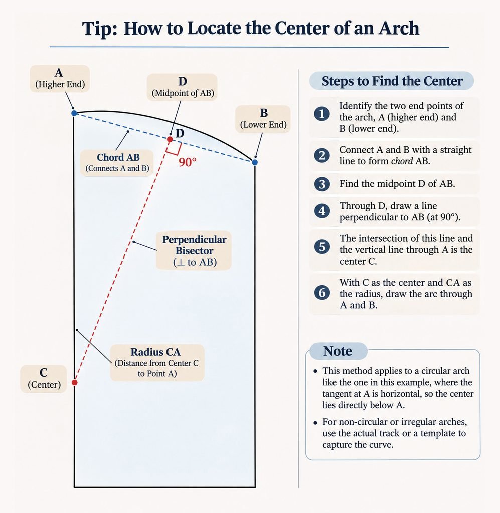
When drafting a circular arch, locating its center can make it easier to reproduce the curve accurately.
The supplementary diagram shows a simple geometric method.
Start by identifying two points on the arch, A and B, and connecting them with a straight line. This forms the chord AB.
Find the midpoint D of the chord and draw a line perpendicular to AB through D.
For a circular arc, the center lies somewhere along this perpendicular bisector.
In the example shown, the tangent at A is horizontal. The center must therefore also lie on the vertical line passing through A.
The intersection of these two lines gives the center C.
Using C as the center and CA as the radius, the circular arc can then be drawn through A and B.
This method is useful when the arch follows a true circular profile. For non-circular or irregular arches, the actual track shape or a physical template provides a more reliable reference.